UML Class Diagram. Design Elements
UML Class Diagram is a type of Structure Diagrams that shows the classes of a system, attributes, operations, and the relationships between them.
Class Diagram is one of important types of UML Diagrams. UML Class Diagrams are used for static modeling of the system, for data modeling, for conceptual modeling of the application, and for modeling of the system dictionary.
On the Class Diagram, Classes are represented as boxes that consist of three parts: name, attributes of the class, and operations or methods.
Use the following notations to set the visibility of a class member: Public (+), Private (-),
Protected (#), Derived (/), Static (_), Package (~). Notation must be placed before the name of class member.
There are a few types of associations between objects and classes on the Class Diagrams.
Bi-directional associations are represented by a line between two classes, it is default connection between classes.
Uni-directional associations are represented as the unbroken lines with an open arrowhead.
Aggregation is an association with the relation between the whole and its parts, and is represented as empty diamond on the Class Diagram.
Composition is a strong variant of aggregation, represents on as filled diamond.
Generalization or inheritance is when a child object or class assumes all properties of his parent object or class, is represented as empty triangle.
There are four notations: 0..1, 1, 0..*, 1..*, that indicate the multiplicity of associations.
The Rapid UML Solution for ConceptDraw DIAGRAM contains 13 vector stencils libraries with 393 interactive shapes that you can use to design your UML diagrams.
To design your own Class Diagram use the UML Class Diagram library.
UML Class Diagram library contains 39 shapes:
- Class
- Class 2
- Object 1
- Object 2
- Self association
- Interface
- Template class
- NARY
- Text Label
- Symbol { }
- Symbol << >>
- Divider (Vertical)
- Divider
- Association without ratio
- Association
- Association One-to-Many
- Association Many-to-Many
- Association One-to-One
- Inheritance
- Composition
- Aggregation
- Inheritance
- Dependency
- Connector
- Package
- Frame, fragment
- Note
- Callout
- Component
- Interface 2
- Realization
- Generalization
- UML Connector (Direct)
- UML Connector
- UML Connector (opposite)
- UML Connector (opposite direction)
- Association (without aggregation)
- Note Connector
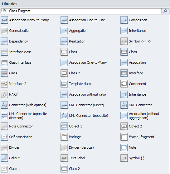
Pic.1. UML Class Diagram Library

Pic.2. UML Class Diagram Library Elements
ConceptDraw Rapid UML solution provides UML Class Diagram library of vector stencils for drawing the class diagrams using class blocks and assembly connectors.
All libraries for creating UML diagrams are available inside the ConceptDraw DIAGRAM Templates and samples are located in the Rapid UML section of ConceptDraw STORE.

Pic.3. UML Diagrams solution
Use design element from the UML Class Diagram library to draw your own UML class diagrams of complex systems and software applications.


TEN RELATED HOW TO's:
UML Class Diagram Notation →
When it comes to system construction, a class diagram is the most widely used diagram. UML Class Diagrams is a type of static structure diagram that is used for general conceptual modeling of the systematics of the application. Such a diagram would illustrate the object-oriented view of a system. The object orientation of a system is indicated by a class diagram. It describes the structure of a system by showing the general issues,classes of a system, attributes, operations, interfaces, inheritance, and the relationships between them. 
Picture: UML Class Diagram Notation
Related Solution:
UML Notation →
There are many ways to track the system in a critical situation. To model a system behavior, uml notation is widely used. Usually, an UML diagram consists of elements such as actor and a case. This diagram represents the structure of UML notations. Unified Modeling Language (UML) is used in software engineering to depict graphically the software modeling process. UM Language uses graphic notations for developing models of object-oriented systems. These notations displays requirements, sub-systems, logical and physical elements, etc. We created this diagram using ConceptDraw DIAGRAM reinforced with Rapid UML solution. It can be helpful for students on software engineering, when learning UML. 
Picture: UML Notation
Related Solution:
UML Class Diagram Constructor →
UML Class Diagrams is a type of static structure diagram that is used both for general conceptual modeling of the systematics of the application, and for detailed modeling translating the models into programming code. It describes the structure of a system by showing the: classes of a system, attributes, operations, and the relationships between them. The Rapid UML Solution for ConceptDraw DIAGRAM includes the UML Class Diagram library that helps you to design the UML Class Diagram quick and easy. You can simply and quickly drop the ready-to-use objects from the library into your document to create the UML Class Diagram. 
Picture: UML Class Diagram Constructor
Related Solution:
UML Class Diagram Generalization ExampleUML Diagrams →
This sample was created in ConceptDraw DIAGRAM diagramming and vector drawing software using the UML Class Diagram library of the Rapid UML Solution from the Software Development area of ConceptDraw Solution Park. This sample describes the use of the classes, the generalization associations between them, the multiplicity of associations and constraints. Provided UML diagram is one of the examples set that are part of Rapid UML solution. 
Picture: UML Class Diagram Generalization ExampleUML Diagrams
Related Solution:
UML Class Diagrams. ConceptDraw DIAGRAM - Diagramming Software for Design UML Diagrams →
In software engineering, a UML Class Diagrams is a type of static structure diagram that is used both for general conceptual modeling of the systematics of the application, and for detailed modeling translating the models into programming code. Use ConceptDraw DIAGRAM with UML class diagram templates, samples and stencil library from Rapid UML solution to show the classes of system, their attributes, operations or methods, and the relationships among the classes. 
Picture: UML Class Diagrams. ConceptDraw DIAGRAM - Diagramming Software for Design UML Diagrams
Related Solution:
ConceptDraw DIAGRAM ER Diagram Tool →
Database design is an important part of any project, as databases become more and more complex nowadays. To make the model more representative, entity relationship diagrams are widely used in software engineering area. These diagrams show sets of entities as rectangles connected via lines labeled with their cardinalities. This an example of the ER-diagram developed to store information regarding some online role-playing game. It includes three main elements of ER diagram: entities, relationships and attributes. The entities, attributes and relationships on this ER-diagram is depicted according to the Chen's notation. Chen's notation for Entity Relationship diagrams admits using of rectangles to depict entities, ovals for attributes and ,at least, diamonds to show relationships. ConceptDraw Entity-Relationship Diagrams solution was applied as ERD software to create this diagram. 
Picture: ConceptDraw DIAGRAM ER Diagram Tool
Related Solution:
ERD Symbols and Meanings →
A database is a data collection, structured into some conceptual model. Two most common approaches of developing data models are UML diagrams and ER-model diagrams. There are several notations of entity-relationship diagram symbols and their meaning is slightly different. Crow's Foot notation is quite descriptive and easy to understand, meanwhile, the Chen notation is great for conceptual modeling. An entity relationship diagrams look very simple to a flowcharts. The main difference is the symbols provided by specific ERD notations. There are several models applied in entity-relationship diagrams: conceptual, logical and physical. Creating an entity relationship diagram requires using a specific notation. There are five main components of common ERD notations: Entities, Actions, Attributes, Cardinality and Connections. The two of notations most widely used for creating ERD are Chen notation and Crow foot notation. By the way, the Crow foot notation originates from the Chen notation - it is an adapted version of the Chen notation. 
Picture: ERD Symbols and Meanings
Related Solution:
UML Object Diagram. Design Elements →
UML Object Diagram shows the structure of a modeled system at a specific time. ConceptDraw has 393 vector stencils in the 13 libraries that helps you to start using software for designing your own UML Diagrams. You can use the appropriate stencils of UML notation from UML Object library. 
Picture: UML Object Diagram. Design Elements
Related Solution:
About UML →
Use Case Diagram Taxi Service UML. This sample was created in ConceptDraw DIAGRAM diagramming and vector drawing software using the UML Use Case Diagram library of the Rapid UML Solution from the Software Development area of ConceptDraw Solution Park. This sample shows the work of the taxi service and is used by taxi stations, by airports, in the tourism field and delivery service. 
Picture: About UML
Related Solution:
Source: https://www.conceptdraw.com/How-To-Guide/uml-class
Posted by: mcwethydorseyees.blogspot.com
